It is widely known that the negative-pressure (also known as acoustic) leak detection method is one of the most powerful methods for detecting pipeline leaks due to the real-time processing of dynamic events in the pipeline, fast response time (within a minute), and ability to locate the leak position along the pipeline with impressive precision.
The operating principle for a negative-pressure (acoustic) leak detection system is elegant and powerful. When a leak occurs, a drop in pressure will happen at the location of the leak. This causes pressure oscillations in the fluid which propagate as pressure wave signals (also known as acoustic waves) at the speed of sound, through the fluid and away from the leak location in opposite directions.
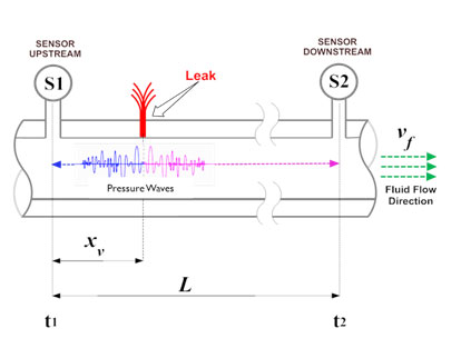
By placing pressure sensors and associated communication equipment along the pipeline, the negative-pressure (acoustic) leak detection system will detect the pressure transient wave associated with the pipeline leak. In the literature the traveling wave is often referred to as a “negative pressure” wave, or the “expansion” wave[1]. The figure below shows the basic concept of an acoustic leak detection system.
[1]Contrary to the common belief, this system is not basedon the audible noise (or sound) produced by the leak flow.Figure 1: Basic Concept in Negative-pressure Leak Detection System
As shown, when a leak occurs, the sudden drop in pressure at the leak location causes oscillations in the fluid pressure that propagate in both directions, upstream and downstream, guided by the pipeline wall. Pressure sensors (designated as S1 and S2) installed at opposite ends of the pipeline protected segment will detect the drop in pressure and transmit the oscillating pressure signals to their corresponding Field Signal Processors (FSP).
The FSP is an integrated field-grade system which includes modules for data acquisition, signal conditioning, noise filtering, data processing and communication. The FSP first applies conditioning and filtering functions to separate leak signals from the background noise, and then applies advanced detection algorithms to determine if a leak “event” took place[1]. The FSPs take into account fluid velocity (Vf), viscosity, pressure, and other pipeline specific parameters. Moreover, all leak events detected locally by the FSPs are time stamped using the GPS system.
The local FSPs at both ends of a pipeline segment then transmit the leak event(s) to the Central Controller (CC) with the time stamp, which analyses events coming from the FSPs. By performing real-time computation and applying a variety of advanced algorithms, the CC declares if a leak has occurred or not, and it will then compute its location.
The location of the leak is computed based on the pressure wave propagation velocity in the fluid, by examining the difference between wave arrival times (t1 – t2) at the two opposing sensors (S1 and S2), and the length of the pipeline segment, as shown in the equation below.
[1] A leak event detected by the local processor (the FSP) represents a possible leak not a definite leak. Only the Central Controller (CC), after correlating readings from multiple FSPs and taking into account a variety of other factors, can declare a leak to the operator.Where,
Xv = Distance from segment end to leak location
Lpipe = Length of this pipe segment
v = Pressure wave traveling velocity in the fluid
t1 = Detection time at sensor S1
t2 = Detection time at sensor S2
It should be noted that not every pressure-based leak detection system is an acoustic LDS system. In fact, many of the pressure sensors (and associated computing equipment) that are commonly used in pressure-based leak detection systems do not qualify as acoustic sensors/equipment due to their slow sampling rate and/or response time.


